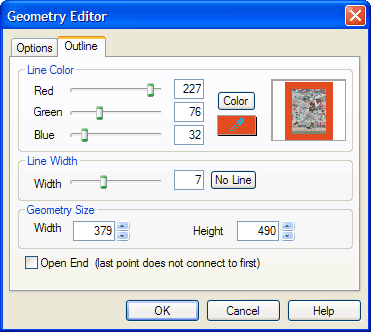
The Outline Tab allows you to change the color, width, and size of a vector geometry (i.e., rectangle, ellipsis, curve, etc.) or add a border to an image.
Change the color, width, or size of a vector geometry or add a border to an image using the Outline Tab of the Geometry Editor dialog box.
When you add a border to an object, by default it will pick up the outline size and color of the last-clicked object (unless it was a text, table or foreign object with no outline). Click an empty place in the Work Window to reset.
Controls on the Options Tab of the Geometry Editor dialog box include the following:
| Field/Control | Description |
| Thumbnail View | Displays the object currently selected for editing. Also shows preview of editing operations. |
| Red | Click and drag the slider left or right to adjust the red hue of the selected geometry. Or, you may enter a value in the field. |
| Green | Click and drag the slider left or right to adjust the green hue of the selected geometry. Or, you may enter a value in the field. |
| Blue | Click and drag the slider left or right to adjust the blue hue of the selected geometry. Or, you may enter a value in the field. |
| Color | Click to open the Color dialog box and select a system or custom color. When you are finished, the values of the selected color will appear in the Red, Green, and Blue fields. |
 |
Click and drag to use the color dropper tool to pick up a color anywhere on your computer screen. Release the mouse button to set the values of the selected color in the Red, Green, and Blue fields. |
| Line Width | Click and drag the slider right to increase or left to reduce the width in pixels of the selected geometry. Or, you may enter a pixel value in the field. The default value is 1. (Not available for image object geometries.) |
| No Line | Click to set the value in the Line Width field to 0. The selected geometry will appear as a dotted line in the Work Window and will be invisible in the Preview Window or when published. |
| Geometry Size | Displays the current width and height in pixels of the selected geometry. Use the spinners to change the width and/or height, or enter values in the fields. . (Not available for image object geometries.) |
| Open End | Click to checkmark to make the last point of the selected curve or polygon geometry unconnected to the first point, leaving it open. Click to un-checkmark to connect the last and first points of the selected curve or polygon geometry, closing it. |
| OK | Click to accept the current settings and exit the dialog box. |
| Cancel | Click to cancel the operation and close the dialog box. |
| Help | Click to open a context-sensitive help topic. |
OR
Click the Object Editor button:  in the Object Bar
OR
Select Object>Object Editor.
The Object Editor dialog box will open.
You may add a border to an image, table, text, title, or foreign object. (You may also add a border to a code object but doing so would negate the invisibility of code objects.)
OR
Right-click the object, and then select Edit Geometry
OR
Click the Geometry Editor button:  in the Object Bar
OR
Select Object>Geometry Editor.
The Geometry Editor dialog box will open.
OR
Click and drag the Color Dropper button: anywhere on your computer screen to pick up a color
OR
Click the Color button to open the Color dialog box to select a system or custom color. For more information, see Color Dialog Box.
OR
Enter a pixel width value in the box.
A preview of the border will appear in the Thumbnail View window.
Since there is not the option of adding space between the object and border or of offsetting the border, you may find these borders do not suit your purpose. Keep in mind that you can also add a separate, independent rectangle object and then group it to join it with the object.

